Skip to content

Major Structural Progress – Hull Expansion, Gun Systems and Aircraft Assembly

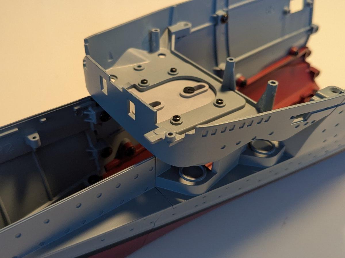
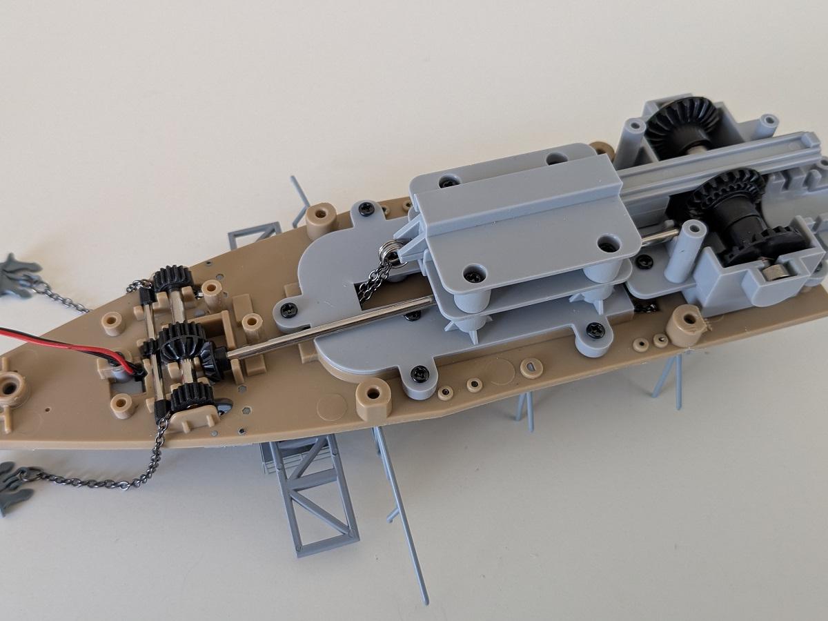
During these construction stages, the Graf Zeppelin model makes significant progress both structurally and functionally. The forward 15 cm gun battery is installed and connected to its mechanical and electrical systems, including LED effects that simulate muzzle fire and a motorized mechanism for gun movement.

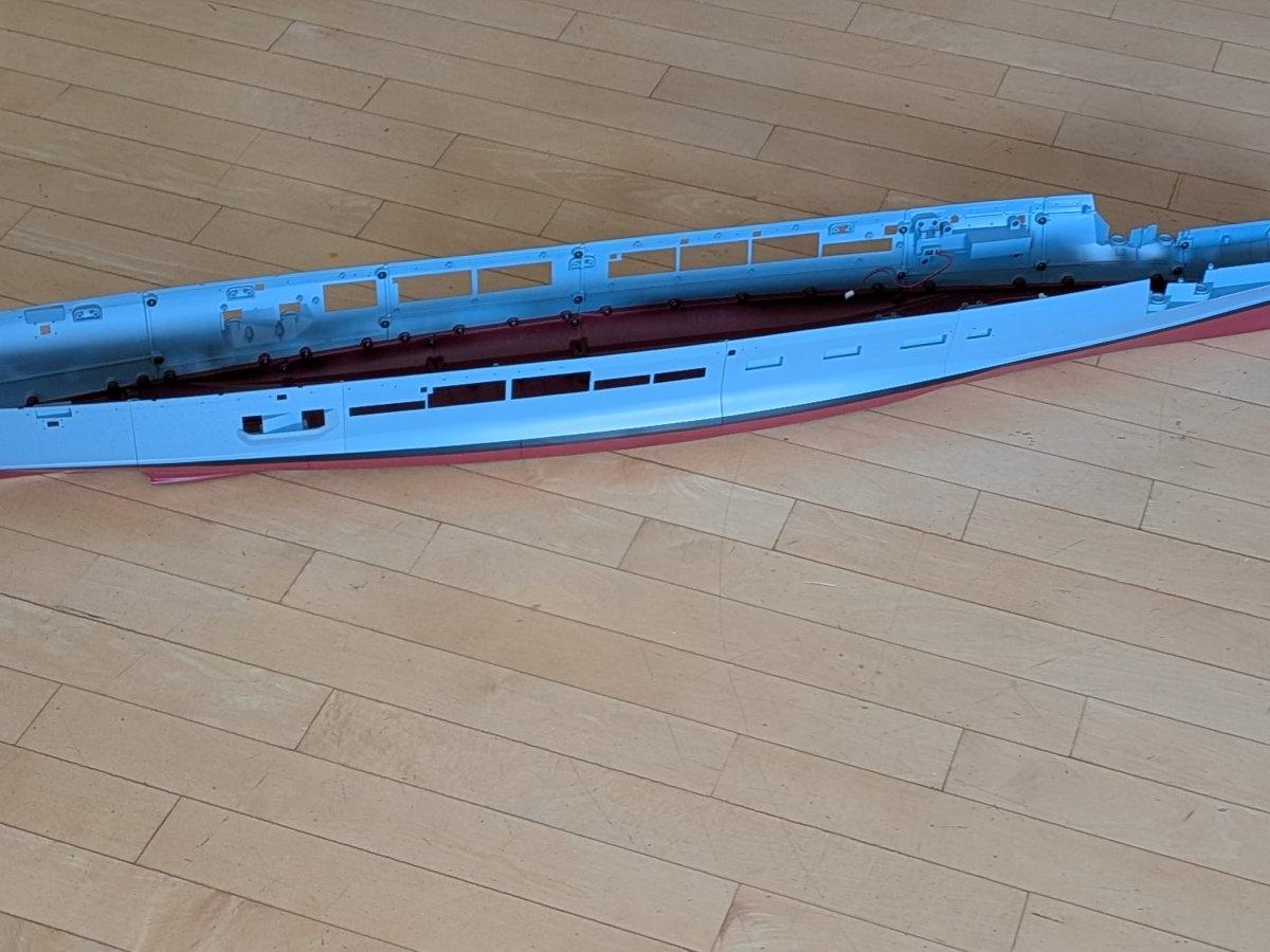
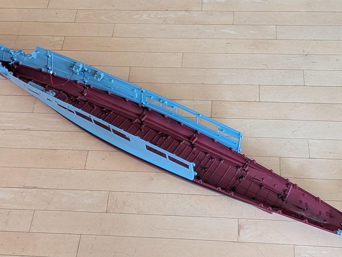
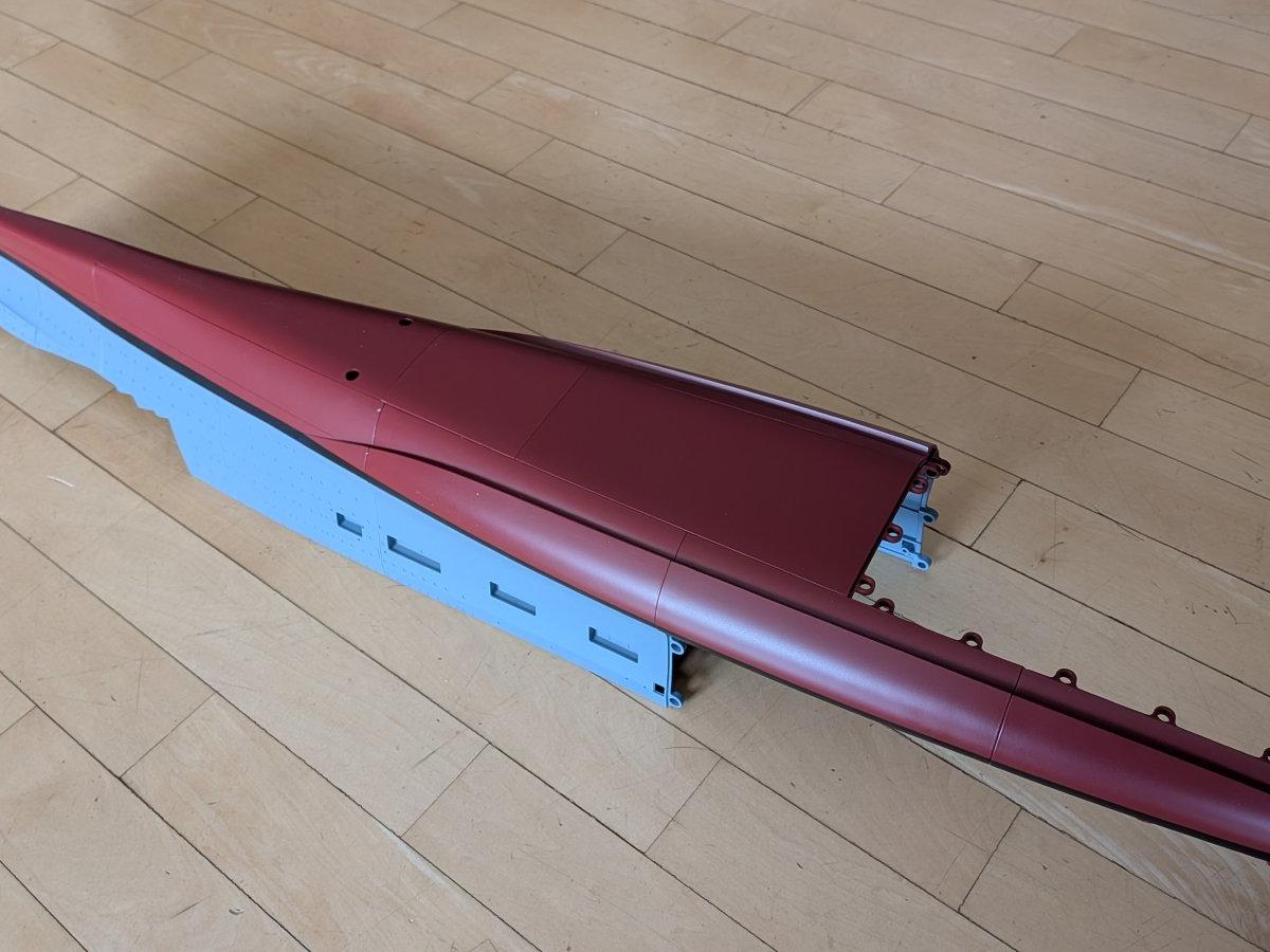
At the same time, the hull grows rapidly as multiple new sections are added to both port and starboard sides. With each extension, the model approaches its final length, reaching about three quarters of its total size. Additional structural components such as keel sections and internal supports improve the rigidity and stability of the hull.

Further detailing includes the installation of navigation lights, photo-etched railings, and internal covers for hull openings. Work also continues on the air group with the assembly of another Ju 87 dive bomber.

Overall, these steps represent a major milestone in the build: the hull structure becomes substantially larger and stronger, key functional elements such as the gun systems are completed, and the model increasingly takes on the recognizable form of the aircraft carrier Graf Zeppelin.

Step 29/140: First 15 cm guns

In this step, the first of the forward 15 cm gun mounts are installed.

The guns, which are equipped with LEDs to simulate muzzle fire, are fitted into the casemattes and then connected to the traverse mechanism. Care must be taken not to tighten the screws too much, as this would prevent the moving mechanism from operating correctly.

Step 30/140: Continue with forward 15 guns.

An additional 15 cm gun is installed and connected to the traverse mechanism.

In preparation for the next construction steps, a small switchboard is added. This unit will later serve as the central junction, combining all electrical wiring required for gun movement and firing.

Step 31/140: Completing the forward 15 cm guns

This step completes the installation of the forward 15 cm gun turrets.

The final gun is fitted, the drive motor for the movement mechanism is installed, and all cables are connected to the switchboard. A functional test is then carried out, confirming both the simulated firing effect—represented by LEDs in the gun barrels—and the elevation movement of the guns.

While the guns do not move independently and instead operate together, which slightly reduces realism, the mechanism works reliably and adds a noticeable dynamic feature to the model.

Step 32/140: Extending the hull

After completing the mechanical installation for the forward guns, this step—and the following ones—focuses on extending the hull. Beginning with the addition of a new underwater section on the port side, the hull length is now almost doubled.

Step 33/140: Building the Hull – Reaching the Halfway Mark

In this step, another section of the port-side hull is installed.

With this addition, the hull has now reached a length of approximately 70 cm, which is about half of the model’s final size. Since the corresponding starboard hull sections have not yet been fitted, there was ample working space, making the installation straightforward and allowing the screws to be tightened easily.

Step 34/140: Hull Detailing Step: PE Railing and Port Light Installation

This time, a photo-etched railing and an internal cover for several hull openings are added. A LED is also installed, which will serve as the port-side navigation light.

Step 35/140: Continue with hull starboard side

With this step, construction of the starboard side of the hull continues. Although only two screws are required, the confined space inside the hull makes tightening them somewhat tricky.

At this stage, the ship’s weight has now exceeded 2 kg.

Step 36/140: Starboard Hull

Work on the hull continues in this step.

An upper hull segment is added to the ship. Since construction has now reached the widest part of the hull, fastening the screws is much easier compared to the cramped and narrow space in the bow section.

Step 37/140: Navigation lights

The starboard hull segment from the previous step was updated with an internal cover to close the hull openings. Unusually, this part is not screwed in place; instead, it is glued for this installation.

The green starboard navigation light was then installed and successfully tested.

Step 38/140: A keel section

Not much work was required in this step — a keel section was added to the hull structure.

This improves the overall stability of the hull. The port and starboard sides are built asymmetrically due to the openings in the upper hull structure, which differ on each side.

Step 39/140: Another Ju 87 dive bomber

This step includes the assembly of a fifth Ju 87 dive bomber. The propeller, landing gear, and four bombs must be attached and securely glued in place.

In addition, two mounting brackets are fitted to the hull. These will most likely serve as the structural supports for the future flight deck.

Step 40/140: Starboard hull extension

In this step, the underwater section of the port side is extended with an additional segment.

The hull now begins to taper again, marking the gradual transition toward the stern.

Step 41/140: Extending the Hull – Starboard Side Expansion

As in the previous step, the underwater section of the hull on the starboard side is extended with an additional segment.

With this modification, the model’s hull length now reaches 95 cm, corresponding to approximately 190 meters on the real ship. The model has now achieved roughly three quarters of its final length, marking another significant milestone in the construction process.

Step 42/140: Strengthening the hull

With the larger keel section installed, the hull structure is significantly strengthened, adding overall rigidity and stability to the entire hull.

This step is very easy to assemble, as access to the screws is not obstructed by other hull components.